lab-aws-cn-series-zero-trust 


Zero Trust AWS CN-Series
QwikLab Guide
Overview
A Zero Trust implementation should provide security administrators with the visibility and the ability to secure traffic between the various applications.
Hands-On Lab – Palo Alto Networks Product Coverage
-
CN-Series Virtual Next-Generation Firewalls
- Protect Kubernetes Containers
- Keep cloud native applications nimble and secure with the industry's first ML-Powered Next-Generation Firewall (NGFW) built for Kubernetes® environments.
-
- Consolidate policy management. Panorama™ network security management simplifies policies across infrastructures and clouds. Seamless integration. Increased oversight.
- Panorama can be deployed as a virtual appliance on VMware ESXi™ and vCloud® Air, Linux KVM, and Microsoft Hyper-V®.
Application Environment Overview
Launch the lab environment
In this section, we will launch the lab environment. These are the steps that we will accomplish at this time.
- Start the lab on your designated Qwiklab account.
- Login to the AWS Console using the provided credentials and set up IAM roles
- Subscribe to the Panorama appliance on the AWS Marketplace.
- Deploy lab environment using Terraform
- Deploy the CN-Series firewalls
- Deploy a sample application for the activity
Start Qwiklabs lab environment and login to AWS
- Once you login to paloaltonetworks.qwiklabs.com, the Home page should display the Labs that you have access to. Identify and click on the Lab that says "Zero Trust AWS CN-Series Lab".

- On the page that opens up, click on CN-Series Zero Trust lab.

- On the Qwiklab environment, Click on Start Lab Button to start the lab.

At this point, Qwiklabs will build an AWS account for you. In order to access the EC2 application instances via SSH in your environment, you will be using keys generated by Qwiklabs. There are two types of keys generated; PEM and PPK keys.
-
If you are on a MAC, you will be using ‘Terminal’ to connect to the devices via SSH. For this, click on the “Download PEM” link. This will download a file named “qwikLABS-L*****-*****.pem”.
- Make sure to note the location where the file is downloaded. On a Mac, by default, it will be downloaded to “/Users/<username>/Downloads”
-
If you are using a windows laptop to access this lab, you will need to have a ssh application like PuTTY installed.
- In this case, click on the “Download PPK” link. This will download a file named “qwikLABS-L*****-*****.ppk”.

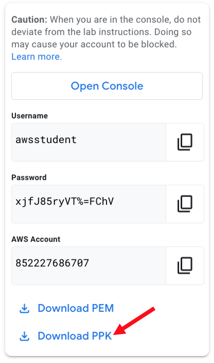
- To login to the AWS environment, right click on “Open Console’ and “Open link in Incognito window” for Chrome-based browsers. For other browsers, use the appropriate option to open the AWS Console in a new private tab.

- On the AWS Console, copy over the IAM username and password from the previous tab.
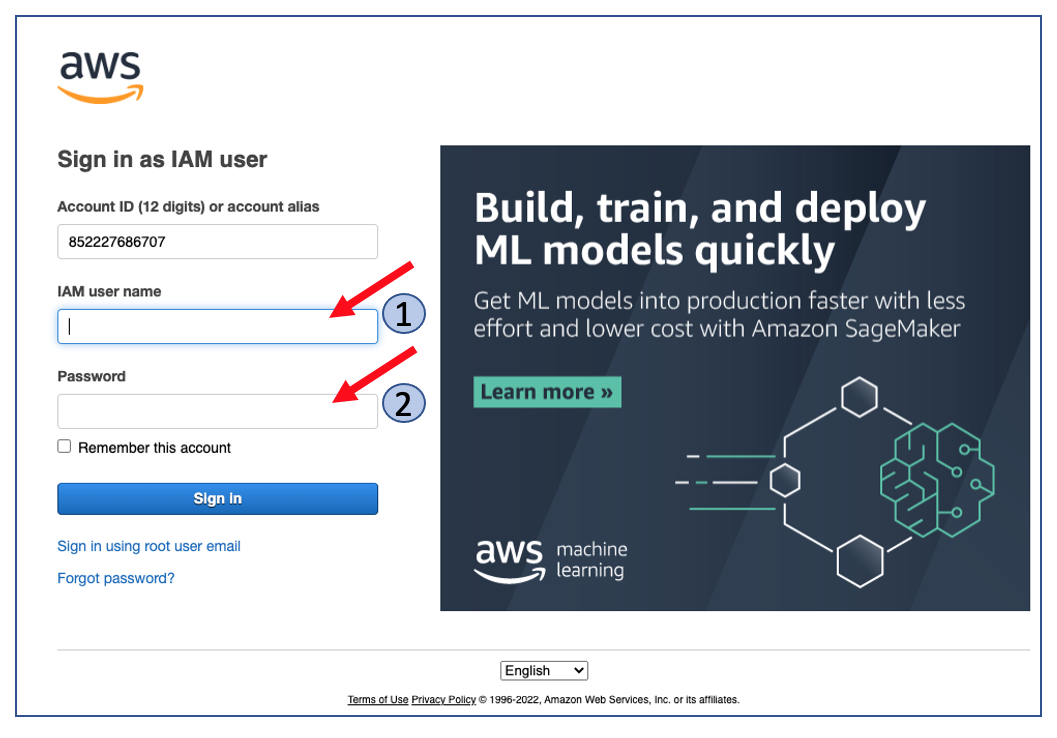

- Now, click on “Sign In”.

Once you are successfully logged in, you will land on the AWS Management Console.

Set up AWS Account permissions
As mentioned earlier, the Qwiklab user account, by default, does not have the permissions to AWS Marketplace and CloudShell services, which are required for the purpose of this lab. We will now edit the permissions for the Qwiklab user account to provide access to those services.
On the AWS console,
- If you see a message for ‘new AWS Console’ click on ‘Switch now’
- On the search bar type ‘iam’.
- Click on the link to IAM. A new IAM dashboard window will open.

- Click on ‘2’ below users.

- Click on ‘awsstudent’.

- Expand the default policy by clicking on the small triangle icon against default_policy in the list.

- Click on the ‘Edit Policy’ button.

- Click the ‘JSON’ tab.

- Scroll down to the Deny policy and remove two lines (line number 27 and line number 36) listed below
"aws-marketplace:\*ubscribe",
...
"cloudshell:\*",
Make sure to delete the whole line.

- Click on ‘Review policy’ at the bottom of the screen.
- On the next screen, click on ‘Save changes’.

- Account setup is now complete.
Subscribe to Panorama on the AWS Marketplace
In this section, we will deploy the AWS Cloud resources required for the purpose of this lab using Terraform.
- Click on ‘AWS’ on the top left hand corner to navigate to the primary console.
- Make sure that the region is N.Virginia.

- Subscribe to Panorama.
- Click on the link below and the page that opens up, Click on “Continue to Subscribe” and then Click on “Accept Terms”.
https://aws.amazon.com/marketplace/pp?sku=eclz7j04vu9lf8ont8ta3n17o


- Wait till Effective date changes from ‘Pending’ to today’s date. This will take a few minutes.

Deploy the Lab resources using Terraform
- From the AWS management Console, launch CloudShell using the icon on the top right side of the console.

If you do not see the icon as shown in the image above, please check the region and ensure that you are in the N. Virginia region.
- Close out the welcome pop up.

It takes around a minute for cloudshell to launch and to get the prompt as shown in the example below.
- After the cloudshell is launched, we will first ensure that the home directory is empty by running the below command.
rm -rf \*
- We will then start by cloning the following github repository:
git clone https://github.com/PaloAltoNetworks/lab-aws-cn-series-zero-trust.git

Figure: Example of cloning the GitHub repository
- Change current directory to git repositories’ root directory:
cd lab-aws-cn-series-zero-trust
- Run the setup script:
./setup.sh
It will take sometime (~10 mins) to deploy all the lab components. Status will be updated on the cloudshell console as deployment progresses. At the end of deployment, you should see the message “Completed successfully!”

Figure: Completion message of the Lab Setup script
- Make a note of the “eks_cluster_endpoint” value as shown in the figure above. This will be used for configuring the Kubernetes Plugin on Panorama at a later step.
- Review the deployed lab environment with the topology diagram shown below.

Figure: The network topology deployed for the CN-Series lab
- On the AWS Console, on the search bar at the top, type EKS and select Clusters from the listed results. For ease of use, open the same on a New Tab, so that we can continue to use CloudShell on the existing tab.
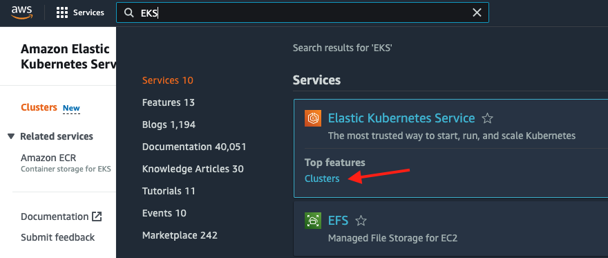
- Review the EKS Cluster that was created.

Deploy CN-Series firewalls and the Application
Before deploying the CN-Series firewalls, we need to configure the public IP address on Panorama.
- On the CloudShell tab, run the following commands. Note the Panorama public IP address.
cd ~/lab-aws-cn-series-zero-trust/terraform/panorama
terraform output

- Open a New Tab on the browser and open the Panorama console using the IP address noted in the previous step. Make sure to add “https://” before the IP address.

- Log in to Panorama management console:
| Username | admin |
| Password | Paloalto@1 |

- Once you have logged in, navigate to Panorama > Setup > Interfaces, as shown in the figure below.

- On the Management popup, enter the public IP address of Panorama as noted before and Click OK.

- On the top-right side of the page, locate and click on the “Commit” dropdown list and select Commit to Panorama.

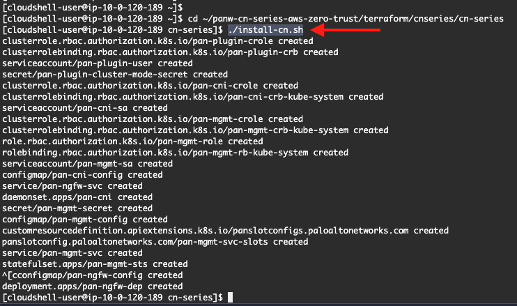
- Navigate back to the CloudShell tab and run the below commands. These commands are to deploy the CN-Series firewalls.
cd ~/lab-aws-cn-series-zero-trust/terraform/cnseries/cn-series
./install-cn.sh
- Now, deploy the sample application by running the below commands.
cd ~/lab-aws-cn-series-zero-trust/terraform/cnseries
kubectl apply -f ./sample-app/guestbook.yml
The deployment of the pods for both the CN-Series and the Sample Application will take around 10 mins to complete. During this time, the deployed CN-Series firewalls will attach themselves to the Panorama as well.
We can review the status of the pods by running the below commands.
For CN-Series,
kubectl get pods -n kube-system

For the sample application,
kubectl get pods -n sample-app

- As seen on the images above, under the READY column, all pods should be 1/1, and under the STATUS column, all pods should be Running.
- Once all the pods are up and running, navigate to the tab with the Panorama console and on the console, navigate to Panorama > Managed Devices > Summary. Note that the CN-Series firewalls were added through bootstrapping.

Configure the Kubernetes plugin
- On the CloudShell tab, run the below commands.
MY_TOKEN=`kubectl get serviceaccounts pan-plugin-user -n kube-system -o jsonpath='{.secrets\[0].name}'`
kubectl get secret $MY_TOKEN -n kube-system -o json > ~/pan-plugin-user.json
This will create a credentials file to be used while adding the Kubernetes cluster in Panorama.
- Download the file by locating and clicking on the “Actions” dropdown list on the top-right side of the console.

- In the Download File popup, enter the following path in the text field and click on Download. This will download the given file into the Downloads folder of your system.
/home/cloudshell-user/pan-plugin-user.json
- Now, we need to also get the EKS API Server Endpoint. Run the below command to change the directory and get the value generated by Terraform.
cd ~/lab-aws-cn-series-zero-trust/terraform/cnseries/
terraform output eks_cluster_endpoint

- Make a note of the value, you will use this when asked for the API Server Endpoint while configuring the Kubernetes Plugin.
- On the Panorama console, navigate to Panorama > Kubernetes > Setup > Cluster and click Add.

-
Enter the fields as given below.
- Name – k8s_cluster
- API Server Address – Use the <eks_cluster_endpoint> value copied from the previous step.
- Type – EKS
- Credentials – Click on Credentials. Browse to the Downloads folder that contains the pan-plugin-user.json file that was downloaded in the previous step.
- Label Filter – “Select All Labels”.
- Click on Validate, to ensure that things are in order.
- Click on OK.

- Configure ‘Monitoring’ by selecting the Notify Group tab, click Add to add Notify Group. Setting up a Notify Group will allow you to segment which Device Group receives notification for changes to a given cluster. This allows for very granular rules.

- Name: k8s-notify-group
- Enable sharing internal tags with Device Groups: Check
- Select Device Group: cnseries
- Click OK.

- Now configure the Monitoring Definition and specify the cluster you created in the previous step. Navigate to Kubernetes > Monitoring Definition > Add. Fill out the Monitoring Definition form:
- Name: k8s-monitoring-definition
- Description: k8s-monitoring-definition
- Cluster: k8s-cluster
- Notify Group: k8s-notify-group
- Enable: Check
Click OK.

- Now that you have created the Monitoring Definition, you can see that the status is Initializing.

- You need to Commit and Push the configuration. In the upper right corner select the Commit Icon then choose Commit and Push.

- In the “Commit and Push” popup, Click on Edit Selections.

- On the Device Groups tab on the popup, check the checkbox against the cnseries device group.

- Navigate to the Collector Groups tab in the same popup and check the checkbox against panorama.
- Click OK.

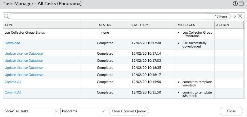
- Check Tasks to confirm all jobs are completed.
- Once the commit is completed, check the status of the newly create Monitoring Definition, k8s-monitoring-definition. The Status should say ‘Polling Connected’
- Click on Dashboard

- You can now see that the Panorama Kubernetes plugin has connected with your kubernetes environment and synchronized the kubernetes tags.

Activity 1: Protect Against Log4j Attack
To secure your containerized application you need to be able to visualize and control the traffic between your pods. Plato Alto CN series firewall allows you to granularly control this traffic.
In step 39 of the previous activity we deployed a ‘Guestbook’ application.The ‘Guestbook’ application a 2-tier simple redis application with a frontend and backend tier. The backend tier will consist of a redis-master and redis-slave for db redundancy. Even though there are two tiers in the application, only one (the frontend service) is exposed to the outside world via a load balancer.
First we would see how having a CN series container Firewall inside your K8s environment gives you visibility to your inter-pod traffic. Then you will use the granular controls using kubernetes tags to control that traffic.
Activity 1a - Gain Visibility on inter-pod traffic
- On the Panorama tab on your browser, navigate to ‘Policies’ and select the cnseries Device Group.

- Review the policies. There is an allow-all policy that will allow access to all traffic.
- Access the web frontend of the two tier application. On the cloudshell window execute the command below.
kubectl get services -n sample-app
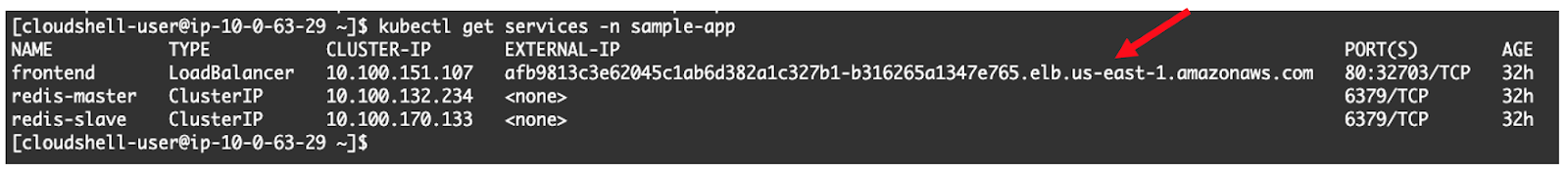
- Copy the URl to a new browser tab and enter.

- Enter ‘Hello World’ on the ‘Messages’ tab and Click Submit
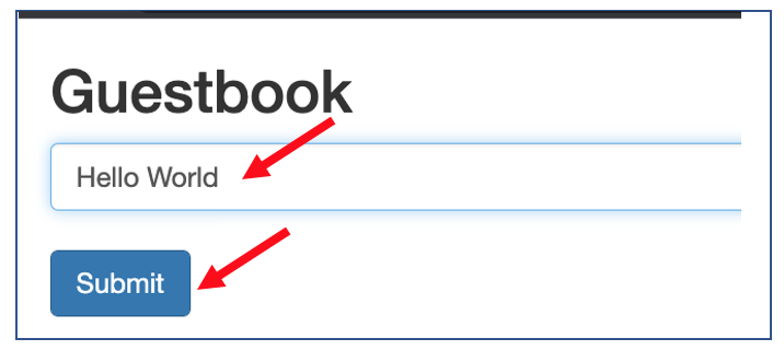
- Guestbook app saves you message in the back end database and prints it back on the webpage.

- Navigate back to Panorama and select the Monitor tab. Under traffic log you can now gain visibility into the communication between the Web Frontend pod and the Backend Database. Note that the CN-Series firewall identifies the Layer 7 application as the ‘Redis’ database application.

Activity 1b- Granular control of Inter-pod Traffic
In this section we will create granular policies on K8s tags and use the policies on CNseries container FW to control interpod traffic
- Navigate to ‘Objects’ tab on Panorama and locate ‘Address Groups’ on the vertical bar and click on Add button at the bottom of the screen

- Name the object ‘Frontend’ and select Type as ‘Dynamic’

- Click on the Add Match Criteria button. This brings up a window that lists all the K8S tags learned from the K8S environment.
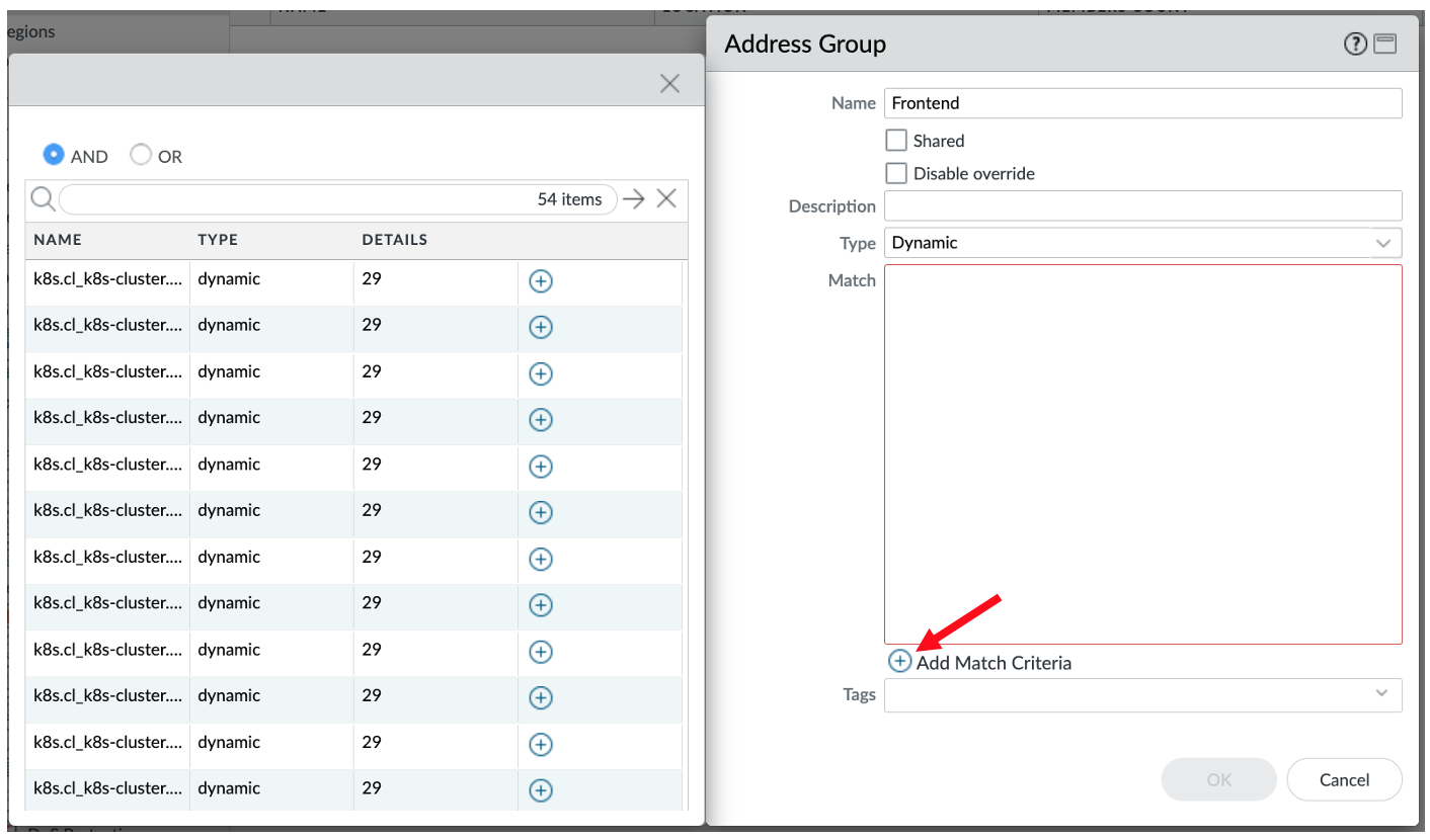
- Now we will define the match criteria to match all tags that have the frontend string. Select “OR”. Type in frontend in the filter and click on the → button.

- Click on the + button against each of the tags to add them to match criteria.
- Click on OK to create the DAG.

- Now that we have created a ‘Dynamic Address Group’ for the web Frontend, let's create a second one for the Backend Database. Click on Add button

- Name the object ‘Backend’. Click on Add Match criteria. Select OR. Type in “redis” on the filter and click →.

- Select all the tags and click on OK.

- Navigate to the Policies tab. We will now use the DAGs to define policy to control traffic from Frontend and backend Pods. Select the first rule by clicking on ‘1’. Click on the Enable button to enable the policy.

- Click on the policy name to edit the policy

- Navigate to the Source tab. On Source address click on ‘+’ and select ‘Frontend’ from the object drop down.

- Navigate to the Destination tab and follow the same method to select ‘Backend’ as destination.

- Navigate to the Application tab. Click on the ‘+’ button, on the search bar type in ‘redis’ and select the application ‘redis’ from the list.

- Navigate to the ‘Action’ tab. Ensure that the Action is ‘Deny’. Click on OK to save the policy.

- Commit and Push

- Ensure cnseries is in the push scope and click on ‘Commit and Push’.
- Wait for all tasks to complete.
- Navigate to the tab where the frontend web page for the guestbook app is open. Refresh the page.
- Type in ‘Hello World Again’ on the message tab and click submit.


- You will see that this time the application will not echo back the message;
- Open the Panorama tab on the Browser and navigate to the Monitor tab and visualize the traffic log corresponding to the firewall policy now blocking the redis application between Frontend pod and the Backend pod of your two tier container application.

Conclusion
As we conclude the exercise, you have familiarized yourself with the basics of EKS (Elastic Kubernetes Service) on AWS, deployed a simple application and secured the network communication between the pods in the deployment using Palo Alto Networks CN-Series appliance.